IP ELRO Peristaltic Pump
![]() The IP Series of ELRO Peristaltic Pumps bring a new range of problem solving benefits to positive fluids transfer for industry.
The IP Series of ELRO Peristaltic Pumps bring a new range of problem solving benefits to positive fluids transfer for industry.
- These pumps have no valves or seals to clog or stick and the pumped medium is in contact only with the inside of the hose.
- Very high viscosity media and delicate suspended solids as well as abrasive mixtures and media with long fibrous and other solids content can be handled routinely.
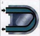
- The patented "Hose-in-Hose" vacuum design enhances inherent peristaltic pumping benefits by improving suction lift, hose life and overall performance, in comparison with conventional designs.
- The self-priming ability of ELRO Peristaltic pumps stems from the near full vacuum achieved by the pumping element. The sealed and lubricated rotor chamber makes it possible to run the pump dry, which is particularly important for the transfer of liquid/gas mixtures.
"Hose in Hose" Feature is an Early Warning Wear Indicator
 |
The red arrow points to |
The patented "hose-in-hose" vacuum system is designed to warn you of imminent hose failure before the hose actually ruptures. This allows you to schedule a hose change on your time, and avoid a messy clean up. The vacuum system also increases suction lift capabilities of the pump, up to 31 feet and it increases volumetric consistency to +/- 1% by reforming the hose bore to its full cross section. Returning the hose ID to its full cross sectional diameter makes it easy to transfer highly viscous products.
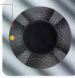
How the "hose-in-hose" vacuum system works: The outer wearing layer of the hose has an internal hose with a capillary tube on the suction side that leads back into the pump casing, above the oil level. (Seen below as the yellow tube, which turns back into the pump housing on the top, suction side, of the pump.) There’s another capillary tube on the discharge side of the pump which leads out to atmosphere. (Seen as the yellow tube venting on the bottom, discharge side, of the pump.) As the rotor crimps the hose to push product in and out of the pump, the "hose-in-hose" capillary tube evacuates the air in the pump housing out to the atmosphere, which creates a near absolute vacuum inside the pump housing. When the rotor wears through the capillary tube, the vacuum in the pump housing will leak out through the rupture.
|
Once the vacuum gauge Automatic alarm option |
The IP series peristaltic pumps come standard with a vacuum gauge, so that you can monitor the vacuum in the pump housing. The time it takes for the pump to develop a vacuum in the pump housing differs, depending upon the application and how fast the pump is turning. Once a vacuum has been fully developed, the pump can maintain the vacuum inside the pump housing for up to twelve hours after the pump has been shut down. Once the vacuum gauge is no longer maintaining a vacuum reading, it is time to schedule a hose replacement.
An optional vacuum switch can be supplied with the vacuum gauge, which can be wired to the motor starter to shut down the pump and/or alarm operators to schedule a hose replacement after the pump has lost vacuum.
Peristaltic Pump Motion - How it Works
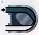
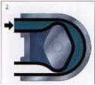
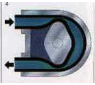
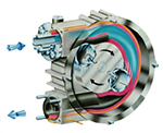
As the rotor tips move within the lubricated rotor chamber, they compress the hose, forming a precise seal between suction and discharge. The pumped medium is transported to the outlet, at the same time creating a vacuum which draws the medium into the suction port. The volume between the rotor tips is half the displacement per revolution. This volume is pumped continuously to the outlet as the same volume is drawn into the inlet.
The Pump Performance Curves
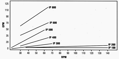
Flow rate is variable by simply regulating speed of rotation and near constant pressure is maintained throughout the range of capacity. Elro Pumps are available in seven sizes with flow rates up to 114 gpm. Standard models are rated up to 87 psi discharge pressure with models up to 188 psi available as an option. These pumps are ideal for fast product change since the pumping element has no dead space and can be easily cleaned by flushing, without need of dismantling.
Dimensional Specs
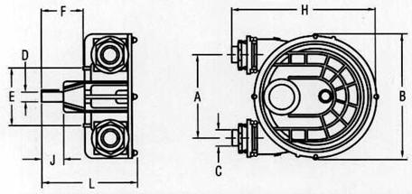
| Dimensions (inches) | ||||
|---|---|---|---|---|
| A | B | C | D dia | |
| IP 100 | 6.02 | 9.84 | 1.00 | 30mm |
| IP 200 | 5.51 | 9.84 | 1.25 | 30mm |
| IP 300 | 13.24 | 18.52 | 1.50 | 35mm |
| IP 400 | 12.69 | 18.89 | 2.00 | 40mm |
| IP 500 | 20.33 | 26.79 | 2.00 | 60mm |
| IP 600 | 20.08 | 26.77 | 2.50 | 60mm |
| IP 800 | 24.40 | 35.43 | 3.00 | 60mm |
| Dimensions (inches) (cont.) | |||||
|---|---|---|---|---|---|
| E dia | F | H | J | L | |
| IP 100 | 7.55 | 6.29 | 13.97 | 2.36 | 10.62 |
| IP 200 | 7.55 | 6.29 | 13.97 | 2.36 | 12.20 |
| IP 300 | 12.21 | 7.17 | 23.04 | 1.37 | 13.79 |
| IP 400 | 12.20 | 6.10 | 22.44 | 3.14 | 14.96 |
| IP 500 | 19.70 | 9.21 | 32.89 | 2.30 | 18.91 |
| IP 600 | 19.68 | 9.25 | 32.28 | 4.72 | 19.68 |
| IP 800 | 24.80 | 11.61 | 39.37 | 5.90 | 26.77 |
Design Specifications
| IP 100 | IP 200 | IP 300 | IP 400 | IP 500 | IP 600 | IP 800 | |
|---|---|---|---|---|---|---|---|
| Flow rate max GPM | 3.5 | 8.8 | 14.5 | 26.4 | 46.6 | 70.4 | 114.5 |
| Hose diameter inches | 0.59 | 1.18 | 1.37 | 1.97 | 2.04 | 2.36 | 2.76 |
| Suction/ discharge connections, male thread, inches |
1.0 | 1.25 | 1.5 | 2.0 | 2.0 | 2.5 | 3.0 |
| HP required @ 87 psi | 1.5 | 1.5 | 3.0 | 5.0 | 7.5 | 7.5 | 15.0 |
| HP required @ 188 psi | N/A | 2.0 | 5.0 | 7.5 | 15.0 | 15.0 | 25.0 |
| Max operating temp | Dependent on medium & hose material, up to maximum of 176 deg F | ||||||
| Suction lift | 31 feet water column | ||||||
| Hose material | Dependent on product, select between Natural Rubber, Nitrile, Butyl, & Hypalon for all sizes. EPDM is available for IP 100 and IP 200 | ||||||
| Bare shaft pump weight (lbs) | 26 | 35 | 105 | 112 | 242 | 271 | 546 |